Steel Hub

A steel plate thickness chart is useful only when it is read as a starting point for a material decision, not as a final specification. It can quickly show the nominal thickness associated with a gauge, imperial fraction, or metric dimension, but it does not tell an evaluator whether that plate will meet bending, load, welding, corrosion, flatness, or weight requirements.
For technical evaluation, the first question is not simply “Which thickness appears on the chart?” It is “What minimum effective thickness does the component need after manufacturing tolerances, service conditions, and any allowance for wear or corrosion?” A plate that looks adequate in a nominal-thickness column can become marginal once those factors are applied.
Reading the chart correctly therefore begins with identifying its unit system, material basis, and stated tolerance standard. From there, thickness selection should move outward to the actual design and fabrication conditions.
Start with the measurement system, then identify what the number represents
Steel plate thickness charts commonly present dimensions in millimeters, inches, fractional inches, decimal inches, or gauge numbers. Metric and imperial dimensions can usually be converted directly, but gauge numbers require more care. Gauge is not a universal thickness designation across all metal products. A gauge value may refer to a specific standard table, product category, or material type. Treating “10 gauge” as a complete plate specification without checking the applicable chart can create a material mismatch.
For plate selection, a decimal or metric thickness is generally clearer than a gauge callout. A specification such as 6 mm, 12 mm, or 0.500 in. establishes a measurable nominal value. A gauge designation should be translated into an actual thickness before it is used in calculations, purchase orders, nesting software, or fabrication instructions.
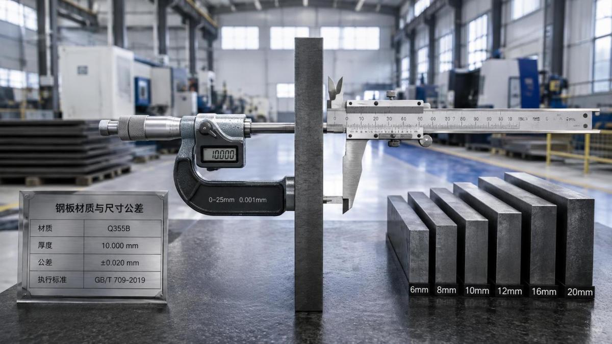
The word nominal is equally important. A nominal thickness is the ordered size, not a guarantee that every point on the plate has exactly that dimension. Rolled steel plate is supplied within a permitted thickness variation. The allowable variation depends on the applicable product standard, plate width, nominal thickness, rolling practice, and sometimes ordered tolerance class.
For a structural member, pressure-retaining part, machined base, or precision fabrication, the relevant dimension is often the minimum delivered thickness rather than the nominal thickness printed on the order. If a calculation requires a 10 mm minimum section, ordering 10 mm nominal plate may not be sufficient unless the governing standard and tolerance demonstrate that the minimum actual thickness remains acceptable.
Do not mix plate, sheet, and gauge conventions casually
Commercial language often blurs the boundary between sheet and plate. In practice, the distinction may vary by market, standard, supplier capability, and end use. Thin flat steel is more likely to be described in gauges, while thicker flat products are normally specified in millimeters or inches. The terminology itself is less important than making sure all parties are using the same actual thickness and product standard.
This issue becomes more consequential when comparing quotations. One supplier may list a gauge number, another may list a decimal inch equivalent, and a third may quote a metric thickness. They may appear comparable while representing different nominal values or different tolerances. The comparison should be normalized to one unit and checked against the required minimum thickness.
Read thickness together with tolerance, not as an isolated chart value
A thickness chart answers “what size is commonly designated by this label?” It does not answer “what section will be present in the finished component?” That second question requires the plate tolerance and the fabrication route.
Consider a plate intended for a load-bearing bracket. Its nominal thickness may be selected from a chart based on the calculated section requirement. But several losses or variations can affect the final part:
- Permitted under-thickness in the supplied plate.
- Local thinning caused by grinding, surface preparation, or weld blending.
- Material removal from machining, countersinking, drilling, or edge finishing.
- Thickness reduction in heavily formed areas.
- Corrosion, abrasion, or erosion allowance during service.
Not every application needs an added allowance for each item. A dry indoor equipment cover and an abrasion liner have very different requirements. The point is to identify which mechanisms are relevant before treating the chart value as sufficient.
Plate width matters as well. Thickness tolerance can vary with width, and some applications are sensitive to cross-plate variation. A wide plate used as a machine bed, mounting surface, or large fabricated panel may need tighter thickness and flatness control than a narrow reinforcing strip. A chart can identify the nominal order size, but it rarely replaces the tolerance language needed for a functional part.
Flatness should also be reviewed separately. A plate can meet its thickness tolerance and still create problems in laser cutting, machining, fixture setup, robotic welding, or panel assembly because of residual stress or shape variation. Where dimensional stability matters, the evaluation should include flatness requirements, delivery condition, cutting sequence, and stress-relief needs rather than relying on thickness alone.
Choose thickness from the governing failure mode
The appropriate plate thickness depends on what the plate must resist. Thickness is often increased as a general response to uncertainty, but that can raise weight, welding demand, handling cost, and distortion risk without solving the actual design problem. The chart should support a defined engineering check.
For plates loaded primarily in tension or compression, the required thickness is linked to the net cross-sectional area after holes, slots, edge clearances, and other reductions are considered. A nominal plate size may look adequate in a gross-area calculation but fail a net-section check near fasteners or cutouts.
For bending applications, thickness has a much larger influence. Plate bending stiffness rises rapidly as thickness increases, so a small change in thickness can materially affect deflection and stress. This is why an equipment guard may remain stable with a modest thickness increase, while a long unsupported panel can still deflect excessively if the span, support spacing, or load path has not been addressed.
For externally pressurized panels, tank walls, covers, chutes, and enclosures, local buckling may control before material yield strength is reached. In those cases, stiffener arrangement, unsupported width, edge restraint, and formed geometry can be as important as the plate thickness selected from the chart.
Where the plate is exposed to impact, abrasion, cyclic loading, elevated temperature, or corrosion, thickness cannot be evaluated independently from steel grade and service environment. A thicker general-purpose carbon steel plate may not provide the same service life as a thinner plate made from a suitable wear-resistant, corrosion-resistant, or high-strength grade. Conversely, selecting a higher-strength grade does not automatically permit a thinner plate if stiffness, fatigue performance, weldability, or minimum practical fabrication thickness governs the design.
Use the chart after the design basis is clear
A disciplined selection sequence prevents the chart from driving the design prematurely:
- Define loads, support conditions, connection details, and exposure conditions.
- Determine whether yielding, deflection, buckling, fatigue, wear, corrosion, or a code requirement controls the section.
- Establish the minimum required finished thickness.
- Add only the allowances justified by tolerance, manufacturing removal, and service loss.
- Select an available nominal plate thickness that maintains the required margin.
- Confirm grade, standard, plate dimensions, delivery condition, and inspection requirements.
This sequence is especially useful when a chart offers closely spaced sizes. Choosing between 8 mm and 10 mm, or between 3/8 in. and 1/2 in., should reflect a documented section requirement and availability check rather than a preference for the nearest familiar size.
Check whether the selected thickness can actually be fabricated
A plate that works in a calculation can still be an inefficient or high-risk choice in production. Thickness affects cutting parameters, forming force, bend radius, weld preparation, preheating practices, distortion control, machining time, and lifting arrangements.
For bending and forming, the thickness chart should be read alongside the specified bend radius and steel grade. A thickness that is easy to form in a low-strength grade may crack at the bend line when paired with a harder or higher-strength material, particularly if the bend direction, edge condition, or inside radius is unsuitable. Material data and fabrication procedures should govern the decision, not a generic assumption that all steel plate behaves similarly.
Welding introduces a second set of questions. As thickness increases, joint design becomes more important. A thicker plate may require edge preparation, multi-pass welding, greater heat input control, and measures to manage hydrogen cracking or residual stress, depending on the grade and restraint conditions. Joining a thin plate to a much thicker plate can also concentrate stiffness changes and complicate weld sequencing.
Cutting method matters as well. Thermal cutting, waterjet cutting, plasma cutting, laser cutting, and machining each have practical thickness ranges, edge-quality implications, and cost profiles. If a component contains tight holes, narrow slots, precision edges, or extensive machining, a small increase in nominal plate thickness may have a disproportionate fabrication cost. The technical evaluator should verify that the chosen size supports the intended process route.
Weight is another direct consequence. Plate mass is calculated from length, width, thickness, and density. Increasing thickness across a large plate area can affect crane capacity, transport limits, installation sequencing, supporting frames, and overall equipment mass. This is relevant in transport equipment, modular assemblies, offshore structures, and large fabricated machinery, where the plate choice may influence systems beyond the individual part.
Common chart-reading errors that lead to material problems
Several recurring mistakes can be avoided with a short review before the purchase specification is released.
- Using gauge without identifying the governing gauge table. Gauge numbers are not interchangeable across every flat-steel product.
- Assuming nominal thickness equals minimum thickness. The ordering dimension must be assessed with the applicable tolerance.
- Comparing different grades by thickness only. Strength, ductility, toughness, corrosion behavior, and weldability may change the outcome.
- Selecting thickness from load alone. Deflection, buckling, fatigue, wear, and service degradation can control instead.
- Ignoring net section. Holes, cutouts, slots, and local machining can reduce the effective area where it matters most.
- Overlooking plate form and flatness. A nominally correct thickness may still be difficult to process or assemble.
- Ordering an uncommon thickness without reviewing supply. Availability, mill rolling ranges, lead time, minimum order quantities, and trimming loss can affect the practical choice.
The last point does not mean a project should always default to standard stock thicknesses. A nonstandard thickness may be justified where weight reduction, performance, or a defined code requirement supports it. It does mean that the selected thickness should be checked against available plate formats and procurement constraints before drawings and bills of material become fixed.
Turn a chart entry into a usable purchase specification
A complete plate requirement needs more than a thickness entry. At minimum, the specification should make clear the nominal thickness, unit system, material grade, governing standard, plate length and width, tolerance requirement where relevant, delivery condition, and any testing or certification requirements tied to the application.
For example, “12 mm steel plate” leaves open important questions: which grade, which standard, what tolerance, whether the plate must be normalized or controlled-rolled, whether ultrasonic inspection is needed, and whether the part will be cut, bent, welded, or machined. Those details should be proportionate to the risk of the part. A simple noncritical fabrication may need only a clear grade and nominal size. A structural, pressure-related, low-temperature, fatigue-sensitive, or heavily machined component needs a more controlled specification.
The practical value of a steel plate thickness chart is speed. It helps evaluators translate between common size designations, compare options, and identify a likely nominal size. It becomes reliable as a decision tool only when that number is tested against the minimum required section, supplied tolerance, material grade, fabrication method, and service condition. Once those checks align, the chart has done its job: it has helped convert a familiar thickness label into a defensible material choice.
Please give us a message
Tianjin Kaichuang Metal Material Co., Ltd
Add: No. 41, District 6, First Street, Huanghuadian Town, Wuqing District, Tianjin
Tel: + 86 137 9101 9833
E-mail: boss@kaichsteel.com