Steel Hub

A damaged edge on a steel coil is rarely just a cosmetic issue. Once the strip enters a slitting line, press line, roll-forming machine, tube mill, or cut-to-length operation, a small nick can become a crack starter, a tracking problem, or a source of recurring scrap. In severe cases, the line must stop because the strip will not run cleanly through guides, levelers, or forming rolls.
For maintenance personnel, the difficult part is that edge damage is often discovered after the coil has already been uncoiled for several turns. By then, the obvious defect may be several meters downstream from the equipment or handling event that caused it. A practical diagnosis therefore starts with the damage pattern: whether the edge is crushed, folded, scalloped, burred, cracked, or intermittently torn. The pattern usually says more than a quick visual check of the payoff reel.
The edge condition may have started before uncoiling
Not every coil edge defect is created by the uncoiler. Steel is produced through ironmaking, steelmaking, casting, hot rolling, pickling, cold rolling, coating, slitting, and packaging steps that can all leave an edge condition behind. The coil may arrive with a trimmed edge, a slit edge, a mill edge, or an edge that has already been affected by transit damage. Those conditions behave differently when tension is applied.
A slit edge can carry small burrs, local camber, or minor deformation from the slitting process. That does not automatically mean the material is unacceptable; the relevant acceptance condition depends on the order specification and the downstream application. But it does mean that the uncoiling line has less tolerance for poor alignment. A sharp guide flange or an overloaded hold-down roll can turn a minor pre-existing irregularity into visible edge tearing.
Incoming inspection should not stop at checking coil width and outer diameter. Before mounting a steel coil, inspect the outer wraps, both edges, the bore, banding marks, and any signs that the coil has been dropped or squeezed by handling equipment. If damage is present on the outer wraps before the coil enters the line, document it before cutting away material. This is important for sorting internal equipment issues from supplier, warehouse, transport, or lifting damage.
Coil handling damage is often underestimated
Forklift contact is one of the most common sources of localized edge damage. A fork tine that touches the coil edge, a coil moved without proper support, or a coil set down on an uneven surface can flatten several wraps at one point. The defect may look like a short crushed section on the edge, but it can continue as a distorted band through several layers of the coil.
C-hooks, coil upenders, mandrel cars, and lifting devices can also cause trouble when their contact surfaces are worn, contaminated, or not matched to the coil geometry. Narrow slit coils are especially vulnerable because there is less edge area to absorb an impact. Coated strip and stainless steel may show marks immediately; carbon steel can hide the damage under oxide, oil, or packaging until the strip is opened.
An experienced maintenance team will compare the position of the damage with handling records and coil orientation. If the same side of the coil repeatedly shows damage, do not assume the steel mill is at fault. Check the unloading route, storage saddles, crane attachments, coil car centering, and whether operators are consistently loading the coil in one orientation.
Misalignment creates rubbing, pinching, and progressive edge wear
Once uncoiling begins, alignment becomes the main mechanical risk. The coil centerline, mandrel centerline, entry table, pinch rolls, guides, leveler, and downstream process centerline need to work as one system. A line can appear acceptable at low speed yet damage the strip edge when acceleration, tension, or coil diameter changes.
If the coil is loaded off-center on the mandrel, the strip tends to walk toward one side. Operators may then close the side guides too tightly in an attempt to correct tracking. That usually makes matters worse. Guides are intended to control lateral position, not continuously clamp the moving strip. When a guide rubs the edge under tension, the result may be polished abrasion at first, followed by a rolled edge or a narrow feathered burr.
Look closely at whether the damage is continuous or periodic. Continuous bright rubbing on one edge suggests persistent contact with a guide, roll shoulder, scraper, or sensor bracket. Repeated marks at a regular interval often point to a damaged roller, a seized bearing, eccentric runout, or contamination stuck to a roll surface. A defect that becomes more severe as the coil diameter decreases may indicate that the payoff geometry is changing beyond the guide system’s working range.
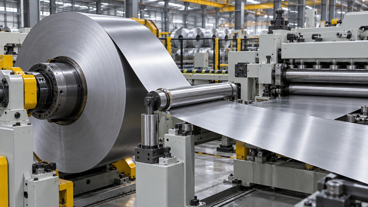
Do not inspect only the components that are easy to see. A worn guide roller can shift under load even when it feels secure during a shutdown check. Bearing play, loose mounting bolts, bent guide arms, and hydraulic drift are all capable of changing the strip path. The line should be checked in its running condition where safe procedures permit, not solely in a static position.
Excessive tension can pull a small edge defect into a larger failure
Strip tension is necessary for stable feeding, especially where the steel coil passes through a straightener, feeder, accumulator, or precision forming section. Yet tension that is too high does not simply make the strip run straighter. It increases the load on the weakest part of the strip, which may be an already burred, nicked, work-hardened, or damaged edge.
This is particularly relevant for high-strength grades, narrow strip, thin gauge material, and products with tight downstream dimensional requirements. A small edge crack that survives low-tension threading may propagate when the line reaches production speed. The maintenance response should not be limited to reducing tension until the problem disappears. That can create looping, poor tracking, and unstable feed. The better approach is to confirm the required tension window for the material and process, then verify that the brake, drive, dancer, and control feedback are actually delivering it.
Payoff brake problems deserve careful attention. A brake that releases unevenly can produce tension spikes at startup. A pneumatic or hydraulic system with delayed response may create similar shocks during acceleration and deceleration. In driven uncoilers, incorrect torque settings or unstable speed synchronization can pull the strip suddenly rather than paying it off smoothly. If edge splits appear near the beginning of a coil, startup tension and threading geometry are more likely suspects than a guide located far downstream.
What the damage pattern can tell you
Worn rollers and trapped debris can cut an edge surprisingly quickly
Rollers are often blamed only when they leave obvious marks across the strip face. In practice, edge damage can occur when a roller has a worn shoulder, damaged coating, sharp burr, accumulated metal particle, or hardened residue near the strip path. The edge contacts the defect first during lateral movement, so a problem may develop before the strip face shows any visible marking.
Cleaning matters, but cleaning without inspection is not enough. A cloth may remove oil and loose debris while missing a chipped roller surface or a damaged scraper blade. Rotate rolls slowly during maintenance, inspect the full circumference, and pay special attention to the locations where strip width changes are common. If the line processes both wide coil and narrow slit coil, contact wear may be concentrated in narrow bands rather than evenly distributed across the roller face.
A seized guide roller is another familiar cause. Instead of rolling, it drags along the edge. Depending on material hardness and line speed, it may leave a burnished groove, a folded edge, or a rough abrasion. The issue can be intermittent if the bearing binds only after thermal expansion or when side load increases.
Payoff setup errors can be mistaken for material defects
Incorrect mandrel expansion is a frequent setup problem. If expansion is insufficient, the coil can slip or shift during payoff. If expansion is excessive, it may distort the inner wraps or create difficulty during coil removal. The correct setting depends on the coil inside diameter, weight, strip width, and the uncoiler design; it should follow the equipment manufacturer’s procedure rather than an informal “feel” developed for one coil type.
The peel-off angle also matters. A strip leaving the coil at an unfavorable angle can rub a hold-down roll or guide before it has settled into a stable path. This is common after a changeover when a different coil width, outer diameter, or strength grade is run without adjusting entry geometry. A setup that works well for heavy hot-rolled coil may not be suitable for thinner cold-rolled material or coated strip intended for appliances, automotive components, or precision fabrication.
Band removal deserves discipline as well. Cutting bands when the coil is poorly restrained can allow the outer wraps to spring outward. The edge may strike nearby components before threading even starts. Follow the site’s coil handling and stored-energy safety procedure, and keep personnel clear of the potential release path.
A practical inspection sequence after edge damage is found
When a damaged edge is discovered, avoid immediately trimming away the affected strip and restarting. That may restore production, but it removes the evidence needed to stop recurrence. Mark the strip position, note which edge is affected, record the coil orientation, and identify whether the damage appeared at threading, low speed, acceleration, steady running, or deceleration.
Then work upstream from the first confirmed damage point. Check the coil itself, mandrel seating, peel-off path, hold-down system, side guides, pinch rolls, and any roller where the strip can move laterally. Look for witness marks: fresh steel dust, polished contact surfaces, coating transfer, oil wiped from one side, or debris lodged at a roll shoulder. These clues are usually more useful than a general statement that “the line was aligned last month.”
If the fault repeats only with one steel coil, quarantine the coil condition as a variable rather than repeatedly adjusting the entire line. If it repeats across different coils and suppliers, the line setup becomes more suspect. If it occurs only at one width, inspect guide settings, roller wear zones, and control recipes associated with that width.
Preventing recurrence is mostly about control, not brute force
Reliable uncoiling depends on preserving the strip path from storage to the first downstream process. That means suitable coil handling methods, clear acceptance checks for incoming edge condition, maintained rollers and guides, repeatable mandrel setup, and tension control that is stable during changing speed and coil diameter. None of these controls is complicated in isolation. Problems occur when minor deviations stack up: a slightly off-center coil, a guide set too close, a roller with bearing play, and a brake response that is a little too aggressive.
For maintenance teams supporting construction steel, automotive feedstock, appliance sheet, pipe and tube production, energy equipment, or rail-related fabrication, the cost of edge damage is not limited to the lost strip. It can disrupt delivery timing and pass defects into a downstream operation where diagnosis becomes much harder. Treat the edge as a functional surface. If it is being touched, pulled, or forced into position during uncoiling, there should be a clear reason for that contact—and a controlled condition for it.
Please give us a message
Tianjin Kaichuang Metal Material Co., Ltd
Add: No. 41, District 6, First Street, Huanghuadian Town, Wuqing District, Tianjin
Tel: + 86 137 9101 9833
E-mail: boss@kaichsteel.com