Steel Hub

Fit-up problems are often treated as welding issues because they become visible at the welding station. Their source is frequently earlier: dimensional variation introduced or retained during steel processing. A plate that is within its thickness tolerance can still create an uneven root opening. A section that meets nominal depth can resist alignment because of sweep or twist. Tube ends cut square to a reference face can still assemble poorly when the tube itself is oval.
For fabrication work, tolerances are not isolated acceptance values. They interact with joint design, part orientation, fixture restraint, cutting method, and the cumulative variation across an assembly. A specification that states only nominal size and material grade leaves too much open when components must fit with limited correction before welding, bolting, or mechanical assembly.
Fit-up is controlled by the combined variation of mating parts
Every joint has an available adjustment range. For a butt weld, that range is governed by permitted root gap, mismatch, edge condition, and the ability to hold parts in position during tack welding. For a bolted connection, it is governed by hole position, member geometry, plate width, and the clearance built into the connection. Once variation in the supplied material, cut parts, and formed components exceeds that available range, rework begins.
A common error is to compare one material tolerance with one fabrication requirement. The relevant condition is the accumulated effect of both pieces. If two plates are each permitted to vary in thickness, the difference between them can be larger than the variation observed on either plate alone. The same accumulation occurs with cut length, flange width, hole location, and section straightness. Assemblies with repeated members amplify the effect because each small departure changes the position of the next locating surface.
Nominal dimensions therefore describe design intent, while tolerance limits describe the possible starting condition at fabrication. Fit-up planning requires both. The question is not merely whether material conforms to a published dimensional standard; it is whether the permitted condition is compatible with the joint and assembly constraints.
Thickness variation changes joint preparation and alignment
Plate thickness affects more than final member weight. It determines bevel geometry, welding heat input expectations, backing fit, and the amount of edge mismatch that can be tolerated. When plates from different rolling lots are used in one welded panel, a nominally identical thickness designation does not guarantee identical actual thickness. The difference may be concentrated near an edge, vary across the width, or be associated with a local high or low area.
At a butt joint, unequal thickness can produce a step between plate surfaces even when the cut edges touch. Aligning one face leaves mismatch on the opposite face. That condition may require a transition detail, local machining, or a decision about which surface controls the assembly. The correct choice depends on function. A pressure boundary, a sliding surface, a fatigue-sensitive detail, and a hidden structural joint do not have the same alignment priority.
Thickness also affects prepared-edge fit-up. If a fixed bevel program is applied to material that varies from the assumed thickness, the resulting root face and included angle vary as well. The welding procedure may still accommodate the joint, but root opening and weld volume will no longer be consistent. Excessive root opening increases deposited weld metal and distortion; a tight root can restrict penetration or make tack-up difficult. This is why nominal thickness alone is a weak basis for setting a cutting bevel on critical joints.
For formed plate components, thickness variation has a second effect. Bend allowance and inside bend behavior change with actual thickness, so flanges formed from nominally identical blanks may not return the same angle or leg dimension. When those flanges later meet a stiffener, cover plate, or mating bracket, the fit-up issue may appear to be a forming defect even though the blank thickness distribution contributed to it.
Flatness and residual stress determine whether plate edges stay where they are placed
Flatness is frequently misunderstood as a cosmetic property. A flatness tolerance describes the departure of a plate surface from a plane under stated inspection conditions. It does not ensure that a plate will remain flat after cutting, bevelling, or releasing it from a fixture. Rolled plate carries residual stress patterns that can become visible after material removal, particularly when long strips, narrow webs, rings, or asymmetrical profiles are cut from a larger sheet.
A plate may lie acceptably on a support table yet lift at one corner once cut into parts. The released component then needs force to sit against a fixture or adjoining member. If it is pulled into place by tack welds, stored elastic strain can contribute to movement during subsequent welding. The resulting joint may begin with an acceptable gap and finish with distortion, mismatch, or a changed overall assembly dimension.
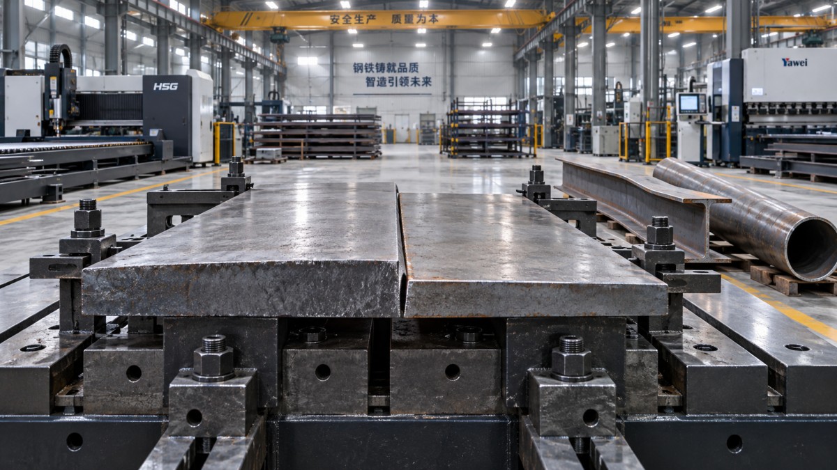
Edge waviness deserves separate attention from general plate flatness. A plate can be broadly flat while its long edges have local waves. In a seam weld, those waves alter the root gap along the joint. In a lap joint, they create intermittent contact and inconsistent clamping. If a plate is intended to nest against a straight machined member, a small edge departure may create a visible gap despite acceptable width and length measurements.
Thermal cutting can add its own movement. Heat input along one edge changes the local stress condition, especially on thin material and long parts. A part that is straight before cutting may show camber afterward. This does not automatically indicate poor incoming steel; it may indicate that material condition, nesting layout, cutting sequence, and heat concentration were not considered together.
Width, length, and squareness affect datum relationships
Width and cut length tolerances become critical when part edges serve as assembly datums. A plate used only as a non-locating cover can accept more variation than a plate whose edges locate stiffeners, bolt groups, or adjacent panels. The distinction should be made on the fabrication drawing rather than assumed from the part outline.
Cut length is particularly important in frames and built-up members. Consider two end plates placed between side members. If both are slightly long, forcing them into the frame can spread the sides or bow the assembly. If both are short, the gaps may be closed with weld deposit, but the intended spacing is lost. Where a sequence of members is located from one end, individual cut-length departures accumulate toward the far end. Measuring each part independently may not reveal the problem until the final closure member cannot be installed.
Squareness has a similar effect. A cut edge that is out of square changes the relationship between nominal length and actual corner position. On a short component, the deviation may be absorbed by weld gap. On a long panel or a precision frame, it shifts the entire mating edge. Plasma, oxy-fuel, laser, saw cutting, and machining do not produce the same edge condition or angular consistency under all material thicknesses and geometries. The required cut quality should follow the joint function, not a generic preference for the most accurate process.
Sections bring straightness, twist, and flange geometry into the joint
Structural sections are often evaluated by depth, flange width, and mass, but fit-up is strongly influenced by their shape along the full length. Sweep is lateral curvature; camber is curvature in another principal direction; twist rotates the cross-section around the member axis. These departures affect different assemblies in different ways.
A member with sweep may be difficult to place against a straight gusset line, even if both ends are located correctly. A twisted angle or channel can leave one leg in contact while the other opens away from the connection plate. An I-section with flange variation can cause uneven bearing against end plates or splice plates. Pulling such a member into contact with bolts or weld tacks may be possible, but the restraint introduced during fit-up should be considered before the connection detail is approved.
Cutting a section to the correct overall length does not correct these geometric conditions. It can make them more consequential by establishing end faces that are used as reference points. When a fabricated beam must meet a column connection at both ends, a local section twist may create a bolt-hole alignment issue that appears only after the member is rotated into its installed orientation.
Copings and notches deserve careful tolerance allocation. Their fit is influenced by the actual flange thickness, root radius, web position, and the reference system used by the cutting equipment. A coping designed from nominal section dimensions may interfere at the root radius or leave an unnecessary opening around the flange. For close-fit details, the actual section profile and the permitted mill variation need to be reflected in the cut geometry.
Tube fit-up requires attention to ovality and wall distribution
Pipe and hollow structural sections create a different set of problems because diameter is often used as the primary descriptor. Roundness or ovality affects circumferential contact at butt joints and the geometry of saddle cuts. Two tubes with the same nominal outside diameter may touch at opposing high points while remaining open elsewhere. This produces a changing root gap around the circumference, which complicates tack placement and weld parameter control.
Wall thickness variation is also significant when branches, sleeves, and end preparations are involved. A bevel generated from an assumed wall thickness may leave a different land around the circumference. At a tube-to-plate connection, a tube that is not truly round changes the bearing line and may make a carefully cut plate hole seem oversized in one direction and tight in another.
Longitudinal seam orientation can matter on welded tube. Where the seam has a local profile difference, placing it at a contact point or saddle intersection may change fit-up. The issue is not that one seam position is always wrong; it is that seam location should be considered when the joint has limited clearance or when multiple tubes must align on a common centerline.
Material standards and fabrication tolerances must be separated, then connected
Material dimensional standards establish permitted product variation. Fabrication drawings establish the dimensions required of finished parts and assemblies. These are related documents, but they are not interchangeable. A steel product can satisfy its delivery tolerance while a finished assembly fails to achieve the drawing requirement unless the fabrication process includes sufficient allowance, correction, or selection of tighter material.
Problems arise when a finished-part tolerance is specified without recognizing the incoming condition. For example, a narrow positional tolerance for features referenced from both plate edges may be unrealistic if the supplied width varies and neither edge is machined or designated as the controlling datum. The fabrication shop then has to choose a reference edge, split the variation, or machine the blank before processing. Each choice changes cost, lead time, and the final relationship of features to the installed assembly.
The inverse problem also occurs: a very tight material tolerance is requested where the fabrication process will dominate final accuracy. If a long plate is subjected to heavy thermal cutting and multi-pass welding, a tighter supplied flatness value alone may not produce a tighter finished panel. Process restraint, weld sequence, heat balance, and post-weld correction determine the result after the material enters fabrication.
Specify the condition that controls the joint
Useful requirements identify the feature that actually governs fit-up. For a welded plate seam, this may be edge straightness over the weld length, thickness matching, and a defined preparation reference surface. For a built-up girder, it may be web straightness, flange edge condition, and end-face squareness. For a tubular manifold, it may be ovality near cut ends, end squareness, and wall thickness at the preparation zone.
Reference length and measurement location matter. “Straight” without a measured length is difficult to apply to a long member. “Flat” without stating whether the plate is free, supported, or restrained can lead to inconsistent inspection results. A thickness reading taken near the center of a plate does not establish thickness at a bevelled edge. Requirements become more useful when they state the datum, the functional zone, and whether the limit applies to the raw product, cut part, or completed assembly.
For assemblies with limited adjustment, it is often appropriate to reserve tolerance where correction is easiest. A non-critical cover plate can absorb variation more readily than a machined interface or a predrilled bolt group. That allocation should be deliberate. Otherwise, the most difficult joint becomes the unintended location where all upstream variation is forced to disappear.
Inspection should follow the fabrication sequence
Incoming inspection is valuable when it prevents incompatible material from entering a constrained job, but it cannot replace part and assembly inspection. The dimensional condition changes as the material is cut, formed, machined, and welded. A practical control sequence uses incoming checks for the characteristics that cannot be economically corrected later, then checks cut parts against functional datums before they are committed to assembly.
For plate work, measurements near planned joint edges are often more informative than a single reading in an open field. For sections, checking straightness and twist over the actual member orientation reveals more than inspecting a short unsupported segment. For tube, end roundness and squareness should be evaluated near the preparation zone rather than assumed from a nominal outside-diameter measurement taken elsewhere.
When a fit-up discrepancy appears, forcing the parts together should not be the first response. The pattern of the gap contains useful information. A uniform gap suggests a cut-size or locating issue. A gap that changes along a seam points toward edge condition, bow, twist, or heat-induced movement. Contact at two points with an opening between them often indicates curvature. A circumferential gap that alternates around a tube joint suggests ovality, end squareness, or both. Identifying the pattern before correction prevents the same condition from recurring in the next assembly.
Steel processing tolerances affect fabrication most sharply where a part has little freedom to move: prepared welds, predrilled connections, mating frames, machined interfaces, and repetitive assemblies. Treating those tolerances as functional inputs, rather than background material data, produces specifications that reflect how the steel will actually be cut, positioned, and joined.
Please give us a message
Tianjin Kaichuang Metal Material Co., Ltd
Add: No. 41, District 6, First Street, Huanghuadian Town, Wuqing District, Tianjin
Tel: + 86 137 9101 9833
E-mail: boss@kaichsteel.com